How to Perform an FEA Analysis Sequence for Battery Systems Without Losing Your Sanity

Andrew Bank
This article explores Finite Element Analysis for battery systems, including how to optimize performance and streamline simulations.
This article explores Finite Element Analysis for battery systems, including how to optimize performance and streamline simulations.
Finite Element Analysis (FEA) is a powerful tool that can either make you look like a genius or leave you questioning your life choices. It’s the computational equivalent of stress-testing your engineering assumptions before reality does it for you in the form of catastrophic structural failure.
When it comes to battery systems, FEA isn’t just a nice-to-have—it’s essential. Batteries undergo mechanical, thermal, and electrical stresses that can lead to anything from performance degradation to dramatic (and highly undesirable) pyrotechnic displays.
So, how do you approach an FEA analysis for a battery system in a way that’s methodical, meaningful, and doesn’t just produce colorful-but-useless simulation plots? The secret is in the sequence.
If you approach FEA like an overly enthusiastic intern hitting “Run” on a mesh-heavy model without checking the boundary conditions first, you’re in for a world of hurt. Instead, follow this three-step structured approach:
Before you start clicking buttons in your favorite FEA software, ask yourself:
Skipping this step is like trying to cook without reading the recipe first. Sure, you might end up with something edible, but odds are it won’t be very good.
Now that you know what you’re solving, it’s time to create a representative model. This doesn’t mean meshing the living daylights out of a high-fidelity CAD file. It means striking a balance between detail and efficiency:
Remember, a model that takes days to run isn’t helpful if it doesn’t provide actionable insights.
Before you trust the results, make sure the model behaves as expected:
This step is crucial to avoid chasing phantom problems that don’t exist in the real world.
Now that we’ve covered the general approach, let’s talk specifics. Batteries are complex beasts, and analyzing them requires a multidisciplinary approach.
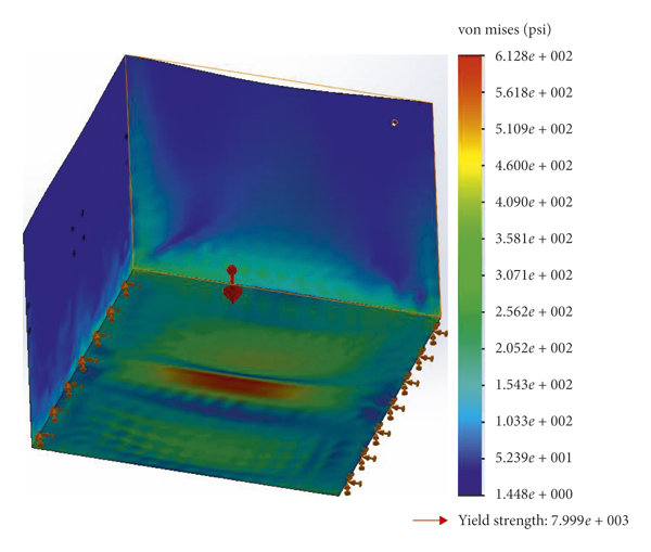
Batteries are subject to mechanical stresses from manufacturing, assembly, and operation. FEA helps predict:
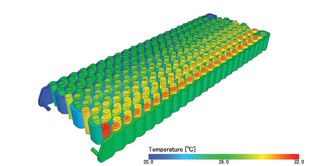
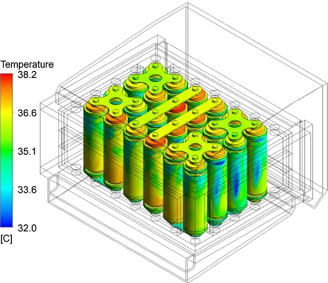
Heat is both a byproduct and a nemesis of battery operation. FEA allows you to:
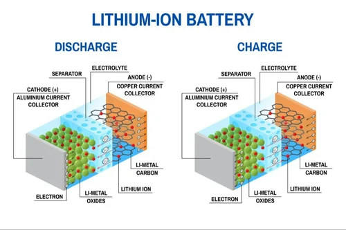
This is where things get really interesting. The interplay between electrochemical processes and mechanical behavior can lead to:
FEA helps predict these interactions before you find out the hard way during testing or, worse, in the field.
FEA is a game-changer for battery system design, but it’s not a replacement for good engineering judgment. A well-thought-out analysis sequence ensures you’re solving the right problems and getting meaningful insights without wasting hours staring at a stubborn simulation that won’t converge.
So, whether you’re designing a next-gen EV pack, a ruggedized industrial battery, or just want to avoid another FEA-induced existential crisis, follow a structured approach. Your batteries (and your stress levels) will thank you.
Now, go forth and simulate responsibly. And remember: if your first attempt works flawlessly, double-check everything—you probably just got lucky.
Treetown Tech is a leading product development company offering comprehensive engineering design services, including, but not limited to, battery prototyping and design, embedded systems engineering services, and system integration services.
No matter what you come to us for, our commitment is to deliver innovative solutions that meet your needs.
Visit our website to learn more about how we work and what we do, or contact us today to get started with a project analysis.
You have the vision. We have the team and expertise to get it built. Let's collaborate to innovate, problem-solve, and de-risk every step of the way.